
Deringer Model 30: How To Repair

I must service a 4” Deringer Model 30. Can you tell me how to change the rubber components for the mainline check valves and the bypass check valve?
Mark:
The Deringer Model 30 is a double check detector assembly. Production began in 2014. The Deringer Model 30 has a type 2 bypass arrangement which incorporates a single check valve. The check valves for the mainline assembly are modular in design. There are no special tools needed to service this assembly. The access cover for the mainline assembly is secured by (6 each) bolts and sealed by an O-ring. There is no spring load on the cover. When removing the bolts, you will notice the bolts have washers that are tapered. These unique washers are needed to help make a water tight seal on the access cover. The check valve modules are secured in the body by retaining bolts located on the outside of the valve body.
Doug:
There are (3 each) retaining bolts on either side of the valve body. Loosen each of the 7/32” Allen retaining bolts until they are flush with the inner wall of the body. The check valve modules are sealed with an O-ring and slide into the body. The first check must be removed before the second check can be removed. Using a flat blade screwdriver, gently pry the module out of the body.


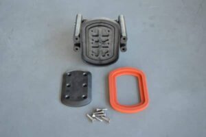
Once the check modules are removed from the body, the check tower can be disassembled from the seat. To do this, remove the 4 tower screws located on the downstream side of each module. The torsion spring is captured and does not need to be retained. With the tower screws removed, the seat is free and can be inspected. The check seat is part of the module. If the seat is damaged, the entire module will have to be replaced. To replace the check disc, simply remove the 6 retaining screws from the disc retainer.


Mark:
When reassembling the check valves for the mainline assembly, it is important to remember that the tower and seat orientation is critical for proper check operation. On check #1 re-attach the tower to the seat with the spring arms and seat protrusions facing UP. On check #2, re-attach the tower to the seat with the spring arms facing DOWN and the seat protrusions facing UP. When reinstalling the modules, check #2 must be installed before check #1.


Once the modules are fully seated, tighten the 6 retaining Allen bolts on the outside of the body. Make sure that the retaining bolts do not bind against the check towers. The last step is to secure the access cover on the main body. Be sure to install the tapered washers in the correct position on the bolts. It is also important to tighten the cover bolts sequentially and by alternating from side to side.

Doug:
On the Deringer Model 30, the bypass check valve is located just downstream of the water meter and is in a 90-degree configuration. The single access cover is threaded into the body and sealed by an O-ring. There is a slight spring load on the cover. The spring and poppet are free once the cover has been removed. To replace the check disc, remove the retaining screw and washer from the poppet. The seat (cage) for the check valve is pushed into the body and sealed by an O-ring. No special tools are required to repair the bypass check valve.