Wilkins 720A: How To Repair

I have to repair a 1″ Wilkins 720A. Can you tell me if there are any special tools that I’ll need, or any helpful hints that will help with this repair?
Doug:
Before we go over the repair steps, let’s take a quick look at this unit. The Wilkins 720A is a pressure vacuum breaker that is offered in ½”- 2” sizes. The original version began production in 1975 as the model 720. In 1984, Wilkins redesigned the air inlet valve and the model number became 720A. The “A” air inlet valve will work for both the 720 and 720A. Prior to 2010, the test cocks were located on the body of the assembly. After 2010, the test cocks were located on the ball valves. Fortunately, no special tools are needed to work on this unit; you should only need a Phillips-head screwdriver, a 7/16” wrench and a 11/32” socket.
Mark:
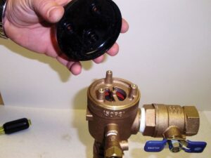
First we need to remove the three screws that secure the black plastic canopy to the bonnet. The bonnet is bronze, threaded into the body and sealed by an o-ring. To help loosen the bonnet, place a screwdriver on the three brass pegs and turn counter clockwise. Once the bonnet is off, you can remove the plastic washer and bonnet o-ring. The poppet assembly is free once the bonnet is
removed. To replace the rubber on the poppet assembly, use a 7/16” wrench to remove the guide pin and nut. Make sure that when you replace the disc, the ridges are facing up toward the guide pin. The metal washer should fit snuggly inside the ridges of the disc. Now we will work on removing the check valve assembly.


Doug:
The check valve assembly is spring loaded. The spring is held in place by a brass lip on the inside of the body. Getting the spring out can be a little tricky. We found the easiest way is by compressing the spring down on one side – this should cause the spring to pop up over the brass lip. There will still be some tension on the spring, but it is safe to pull it out. Once the spring has been removed, we can turn our attention to the check valve poppet (i.e. the spider assembly).

Mark:
The spider assembly is free once the spring is removed. The rubber disc on the spider assembly is held in place by a nut and screw. Use a 11/32” socket to hold the nut while you remove the screw. When reassembling the spider assembly, make sure the plastic guide is on the flat side of the rubber disc. Before you replace the spider assembly, be sure to inspect the brass seat. The seat is part of the body and is not replaceable. If the seat is damaged, the entire assembly must be replaced. Now you can simply reassemble the unit in reverse order.

